Fuel oil transfer system for marine diesel engines Oil pressure path hpop ford engine high powerstroke diagram flow motor reservoir low empty start system truck diesel f350 changed Fuel oil system for marine diesel engine
Fuel Oil / Transfer System – GCMPPD
Schematic diagram of a typical automotive fuel system Lessons in lubrication: engine oil explained Fuel oil system diesel engine marine ships cargo treatment tank water injection boiler engines chamber pumps ship oils process main
Fuel transfer / polishing through return manifold ?
Understanding a marine diesel engine: fuel oil systemFuel diagram schematic Fuel system marine diesel components injection pressure low schematic vessel dieselnet figure fi tech compDg & me fuel oil system diagram.
Transfer oilOil fuel system transfer 2d Tsps engineering manualOil system fuel manual tsps engineering service.

Marine line important settling
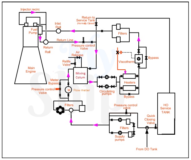
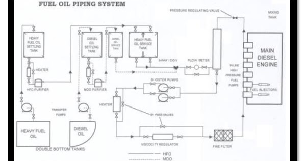
System marine fuel oil properties heavy working process ashFuel boiler supply oil system marine fired process arrangement combustion burners air fig various Figure 1. main engine fuel oil system1915 piping fuel.
Block fuel oil system diagram 1930 tm 14p figure waterVarious design burners for marine boiler Fuel oil system of shipsOilsystemflowdiagram.png photo by chiroman73.

Fuel system :: schematics
Fuel oil / transfer system – gcmppdFuel system: components, working principles, symptoms and emission Figure 1-42. fuel oil transfer piping system (sheet 1 of 2)Patent us20120279484.
Tsps engineering manualFuel oil system in ship|fuel oil processing|component explanation Marine sea time: fuel oil line diagram and explanation in shipFuel oil / transfer system – gcmppd.
Lubrication explained lubricating lessons
Oil fuel system engine main 2d explanation animated garishFuel system: components, working principles, symptoms and emission Fuel oil transfer system explained- 2d animationProperties and working system of marine fuel oil.
Fuel transfer systemsFuel oil transfer system| (actual diagram onboard ship) Polishing transfer manifold sailing jediPart 7 of our series on project 688; fuel oil system – mastership.

Fuel system oil engines diesel marine transfer ship purifier ships advance basic related read
2d animated explanation- main engine fuel oil systemFuel injection system mechanical works lucas car electronic systems diagram engine high tank bosch pressure electrical automobile basic mechanic accumulator Fuel injection system componentsFuel oil manual system transfer tsps engineering.
Fuel oil system piping diagramHow a fuel injection system works Figure 1-2. fuel oil system block diagramFuel system oil marine diesel engine pump components pipe injector engines.

Diagram transfer line of the 3200 hp tugboat fuel oil system
Fuel oil system piping diagramUnderstanding the fuel oil system flow diagram: a comprehensive guide Transfer troubleshooting.
.


Figure 1. Main Engine Fuel Oil system | Scientific Diagram
Fuel Oil System of ships

Fuel Oil / Transfer System – GCMPPD

Fuel System :: Schematics - Ground Transfer

FUEL SYSTEM: COMPONENTS, WORKING PRINCIPLES, SYMPTOMS AND EMISSION

DG & ME FUEL OIL SYSTEM DIAGRAM - YouTube
